As you have probably read few weeks ago the work with Marco Signorini (Ethermania) is going further and the design stage is basically completed, so lets start to have a look in.
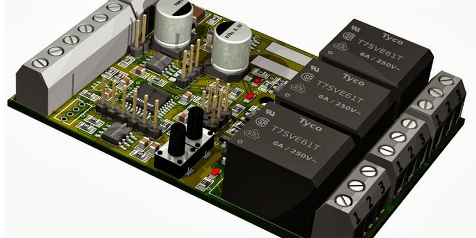
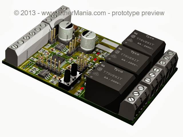
The first rendering on the top shows the multichannel LED board, compared to the first release unveiled in the forum, now there are two separate ground plane that are joined at the two faston connector type in the center of the board. This avoid that high current from MOSFET flows in the same path used by the microcontroller and the transceiver. As main power there is a bus at 24V converted with a DC/DC switching regulator (estimated efficiency > 70%), an additional power supply is required to power the load (as LED strips). The board will handle 2.5A per channel for a maximum of 30A that cannot be supplied from the bus due to the cable resistance and size. It would be possible to use one locally power supply and adding an external diode, the board could be used to power relays or electro-valves.

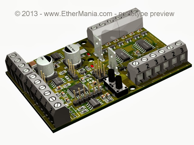
On the relay board side there are no big news, the two board share the same design for the left-hand side of the PCB. In that side there are the DC/DC switching regulator, the RS-485 transceiver, the inputs and the microcontroller.
There will be more board in these series, all are based on the ATmega328P as the Arduino UNO, Arduino Ethernet and Arduino Duemilanove. The load of the sketches need an external USB to USART converter as per Arduino Ethernet and many other boards thinked to be embedded and not programmed so often.
More info in the forum.
Stay tuned, Dario.