
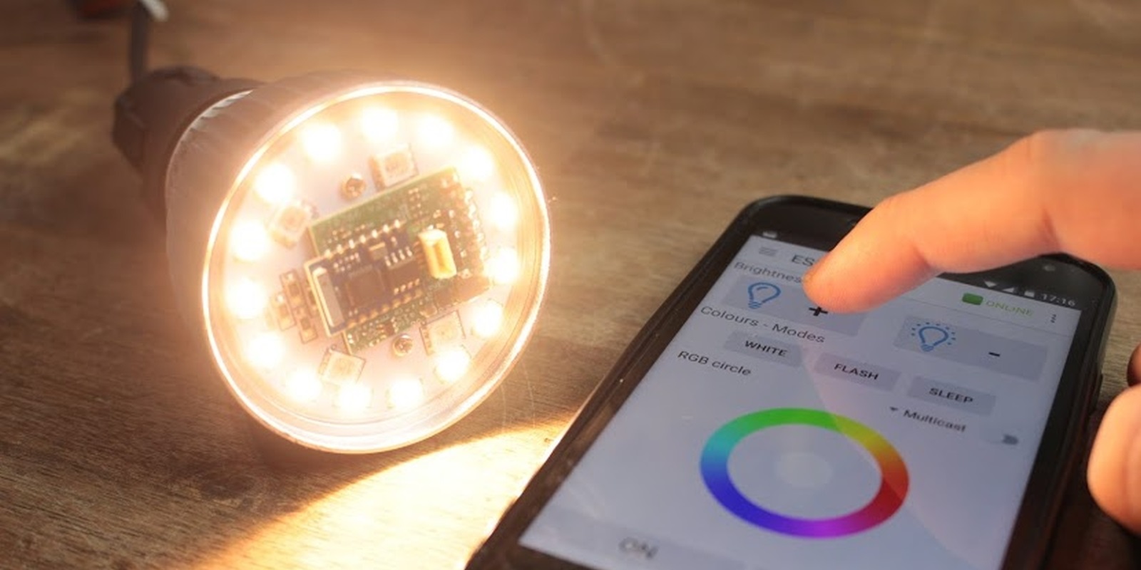
Recently GreatScott published an interesting video on the LYT bulbs by Authometion, he focused his interest mostly on power consumption and measured a very low efficiency and high power consumption for the LYT, he honestly admitted that his math was wrong, but lets go deep inside.
Let’s start from the result, the LYT88 consume approximately 8.7 W at full bright and has an electrical efficiency of 81%.
Now, take a bunch of minutes to see his video and read some comments
In the comments some users point out that those measure can be affected by the reactive power and for this reason GreatScott has posted as errata corrige new measures and some scope waveform.

This picture has shocked me, it shows the voltage and current waveforms for the LYT bulb at full bright, is not a sinewave at all. None of the standard theory applies in these cases and I discovered that myself as many others has too little knowledge on how to measure the power for such type of device.
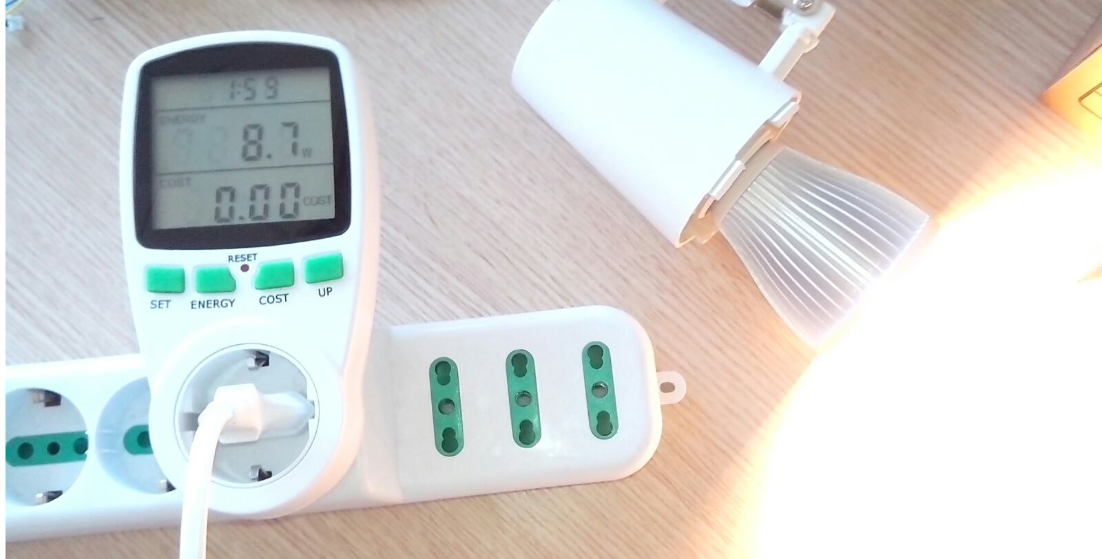
LONG STORY SHORT: If you want to measure power, don’t fight with math! Use a power meter
Using a power meter is easy and quite cheap, the one in the picture isn’t a professional device but give an accurate enough measure to understand the power magnitude.
Now the question is, were the measure posted by Scott in the errata corrige right? The answer is a big no and we will see below the reason.
WHAT’S THE REACTIVE POWER
Powering a not resistive load like an electric motor with a sine-wave result in a sine-wave current with a different phase, from a physical point of view the device it self will source back some of the power that has sink. That portion of the power doesn’t produce any work because has a zero average value and is called reactive power.
Isn’t clear? The picture below shows the voltage, current and power for a resistive load (top) and inductive one (bottom). In case of an inductive load the power cross the zero and has negative values, while negative the load is sourcing back some of the power that has sink before crossing the zero.
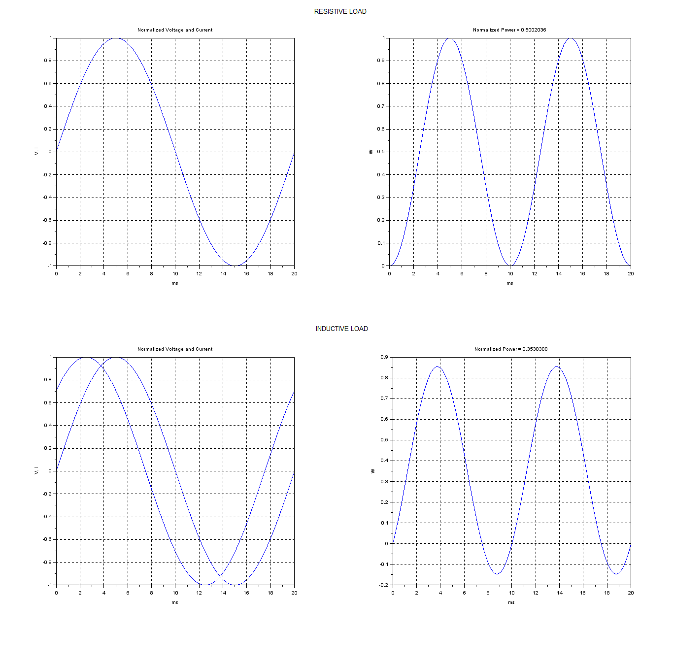
In both resistive and inductive case, has been used normalized (1 V and 1 A magnitude) waves so you have the same peak value but different power values. That’s the reason why you cannot simply measure the magnitude and get the power, the angle position of the waves matters.
Without diving in details, you can use the cosine function of the angle between voltage and current (known as cosphi) to get the active power from the magnitude values. The active power is the one that does the work and is the one that you pay in your home bill. So, Scott has posted new measures and math using standard calculation that applies for sine-wave and has applied to the LYT that has a current that isn’t a sine-wave.
ESTIMATE THE POWER FOR A NOT SINE-WAVE CURRENT
There are multiple way to proceed but here we follow the short path, computer does the math for us and we can just apply the power formula, multiply voltage and power in a time constrained integral. Nowadays is easy, you just need to export the values from the oscilloscope and use a great tool like Scilab, but Scott didn’t exported the values.
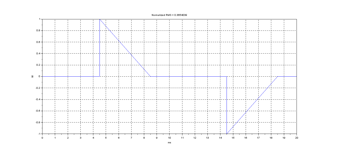
So an estimation can be made calculating the normalized power of a voltage and current waveforms that are near to the one in the oscilloscope, here the code
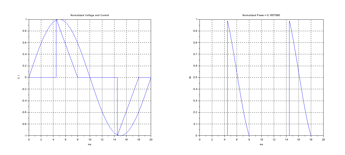
The power waveform is always greater than zero and there is no reactive power but is too far from a sine-wave to apply any standard math, a discrete integration of that wave gives a normalized power vale that’s useful because is the scaling factor to be applied once we know the magnitude values. This is the equivalent of the cosphi for our wave.
WHAT A MULTIMETER MEASURE
So now we just need the magnitude (maximum value in the wave) for both current and voltage, easy? Not at all!
Without the values from the oscilloscope (because we don’t know the scaling factor and Scott hasn’t provided details about) the only source of information is the multimeter. In the video Scott has used a nice True RMS multimeter, so the measure is the mean square root value and not the peak value.
Using the measure from the video we have and applying the following scaling factor we can get the peak value
| Measure | Waveform | Scaling Factor |
|---|---|---|
| Voltage | Sinewave | 1/0.707 |
| Current | - | 1/0.365 |
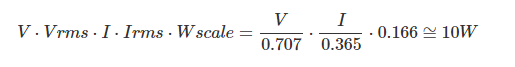
The scaling factor of the current can be calculated as the RMS of the normalized wave
So, using the scaling factor we can get the peak values and applying the normalized power value we get the estimation of the power consumption as 10 W, that’s an estimation because the wave form was just a raw shape from a picture and not an export from an oscilloscope.
These 10 W are a most reliable estimation and shows the proper way to follow, at the end the long story short is the way to proceed, using a watt-meter that shows 8.7 W used on the AC side.

Back to the efficiency, the measure on the DC side at full bright are free from PWM and are supposed to be mostly constants because the microcontroller power consumption (that is clock driven) is negligible compared to the LED ones at full bright. So the 7.05 W on the DC side can be considered a good measure and compared to 8.7 W on the AC side gives a good 81% of efficiency.
UPDATES
Gabriele has a professional meter and after reading the post has done some measures on the bulb. I’ve got the export from his scope and applied the integral into a period of time to get the average power on AC and DC side, with a 82% efficency as result in the case of 2.5 W consumption on the AC side.
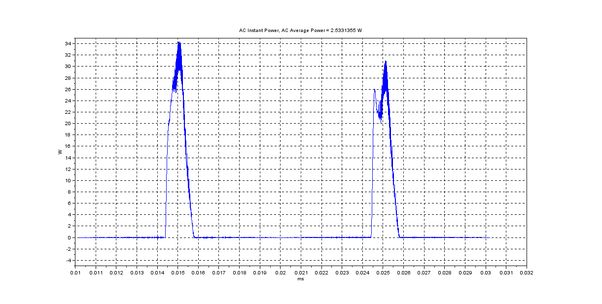
The measures as well as the Scilab code to get the plots are available here.
Enjoy!