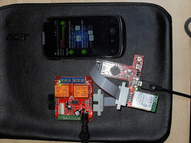
What you can see in the picture is one of the most important goal of the project, make things speak easily, this time using a custom build node using the UEXT connector. It’s basically a Lego-style job, using a ribbon cable and the Souliss framework you can get a running node in half an our.
This is a cheap WiFi node with two relays and 7 GPIOs, controlled via Android or Modbus TCP. Is build over three modules, the main is the AVR-T32U4 an Arduino Leonardo compatible board in T shape, connected to MOD-WIFI and MOD-IO2.
As usual, the Souliss framework allows you to build a full network of nodes that can exchange data and actions, no matter for the hardware that is used or the communication interface.
The steps to get this node running are very few, download the Souliss framework to load on your AVR microcontroller and then install the Android application on your smartphone. You can get one solution from the many supported, in that case all hardware is from Olimex and the ribbon cable is a custom made bought on Ebay.
Please pay attention if you are planning to use MOD-WIFI, because support is restricted to some production models.
Once you have all your components, take the ribbon cable (1 female, two male connectors) and remove from one of the male the two pins dedicated to I2C as in the picture. This hack is required because UEXT is not born as a shared bus, and in not I2C boards these pins are used for the interrupt. Once you free these two pins, you can connect there the MOD-WIFI (or another supported SPI module) and on the other male the MOD-IO2.
Finally plug the microcontroller board into and give power. As first test, power the AVR-T32U4 using an USB cable, that will be used also for Souliss download, wait for the connection process of the WiFi module and then start to play.
As you can see in the picture, the Android application allow to control the relays and give also a feedback of the actual state of the board. The relays state can be changes also from the pins of the green terminal strip, using the first two GPIOs, then the new state will be reported to the smartphone or any other (like Modbus) user interface.
Now that all is working fine, the next step is powering the microcontroller straight from the MOD-IO2, there is an SMD jumper that if closed let the MOD-IO2 power all the chain, so no longer need for the USB cable. Please be careful and don’t connect both the power supply of MOD-IO2 and the USB cable once you have closed that jumper. For further upgrade of the code, you will need to disconnect the MOD-IO2 and power the AVR-T32U4 via the USB cable.
Then, start building your network and interconnect your things using Souliss.