
Recently a lot of RF light bulbs with smartphone enabled control has been on the market, the most known and expencive is the Philips Hue, but other cheaper solution like the Mi-Light has been out for a while. All offer a smartphone app to control remotely the brightness and the color, but none is Arduino compatible.
In this video we review the LYT bulbs from Authometion, the first Arduino controlled light bulbs. Here instead of have a gateway that bridge your smartphone to your lamps you have an Arduino shield, this enable you to make your own Philips Hue like bulbs.
In the video we runs Souliss as framework and control the light with SoulissApp, below you can find a step by step guide to get it working.
Overview
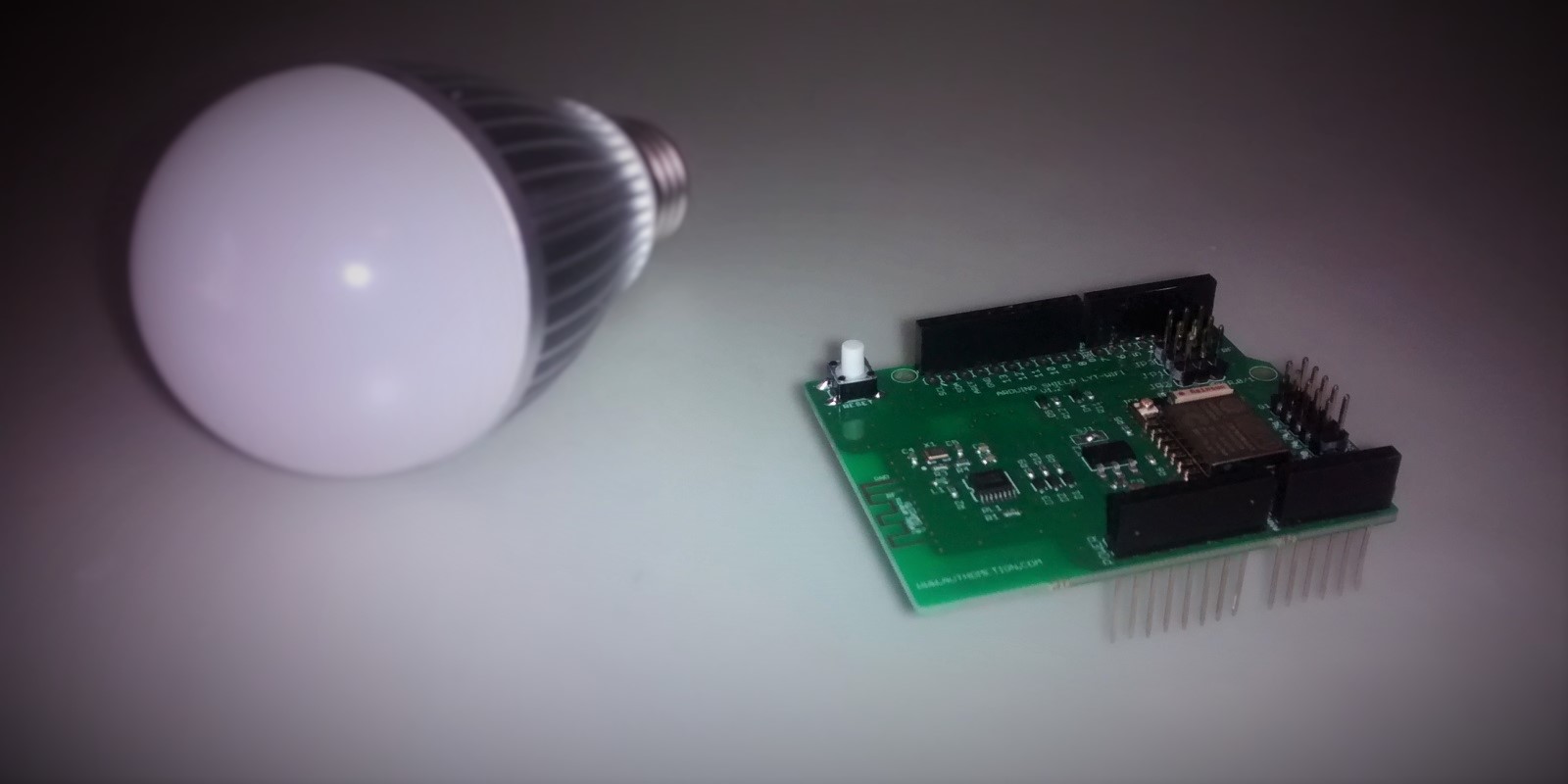
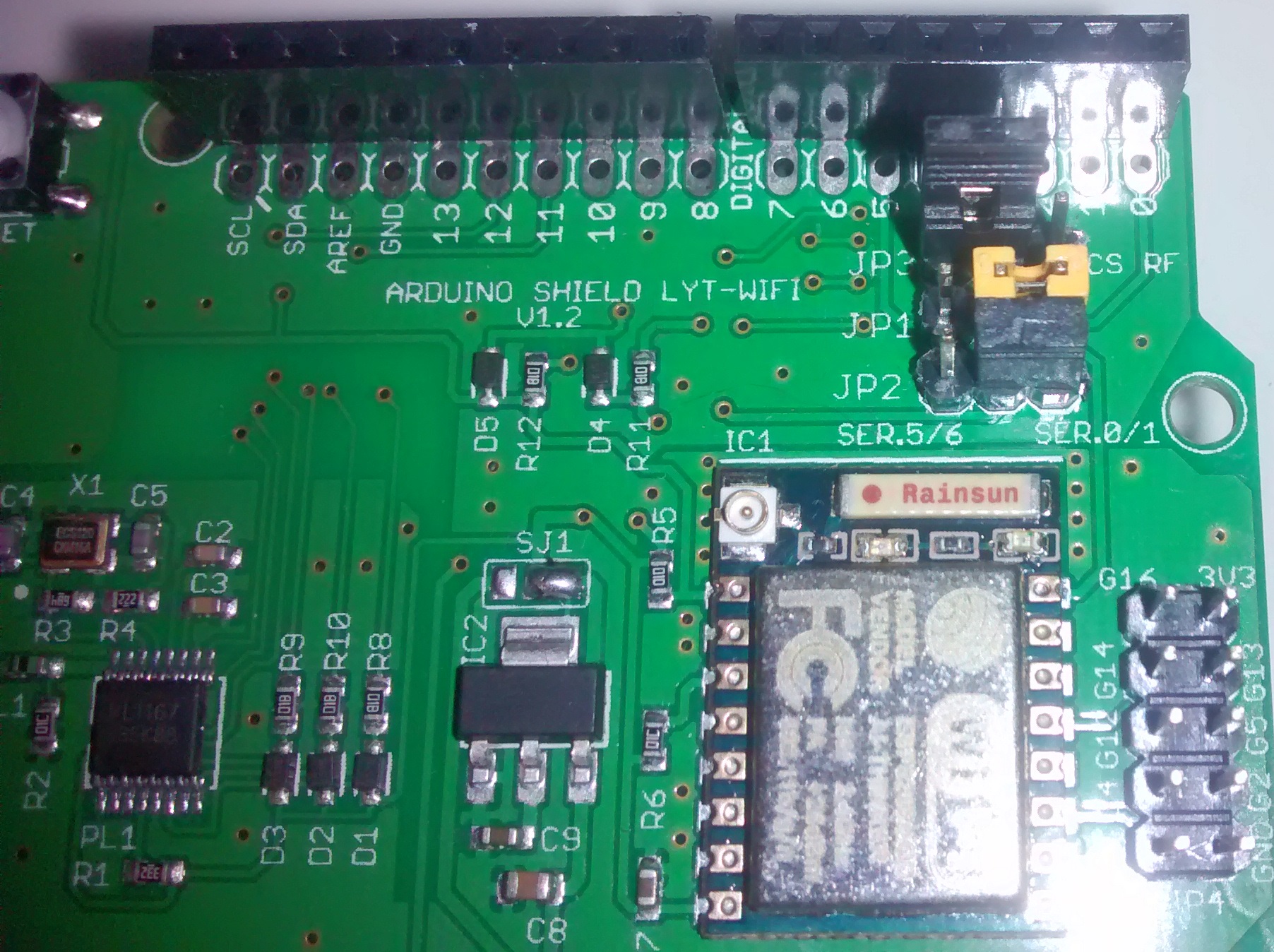
The shield is the piece of hardware that you are really looking for, is from that one that you can send radio commands to the lamps and get feedback. There are two radio, an ESP8266 WiFi SoC and a PL1167 2.4 GHz radio, the former is used to connect your Arduino with the home router and the latter is to control the bulbs.
The PL1167 is a SPI radio wired to the microcontroller of your Arduino board (UNO and Leonardo are the most appropriate), the ESP8266 and the Arduino are connected via USART. From the Authometion store you can download the libraries and examples, those allow you to bridge command via WiFi to the USART and then to the PL1167. A mirror copy with few modification to integrate with Souliss is available on our Google Drive.
In our case we will not use the Authometion examples, but a Souliss dedicated one, so that you can get control of your bulbs directly from SoulissApp or openHAB.
We will run two instances of Souliss, one on the ESP8266 and the other on the Arduino board, this because Souliss embed the communication between different nodes and this let us skip the writing of a custom code to link these two devices.
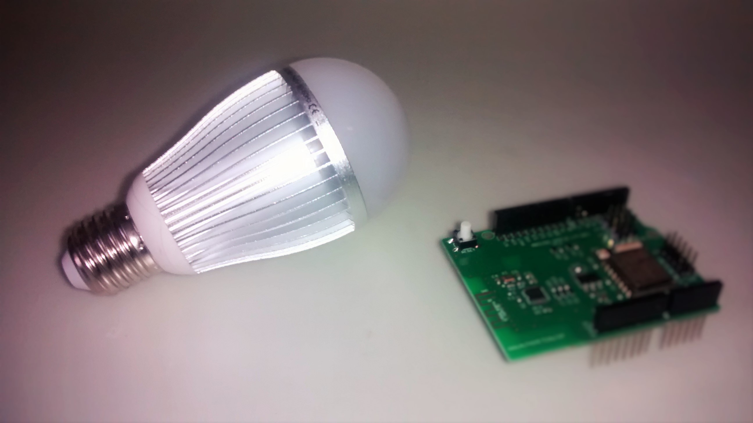
The bulb is a 9 Watt with RGB+W LEDs, the white has a very good bright and colors allow to create moods effect with a good color depth, is bigger than standard bulbs but smaller than other radio controlled ones. It should generally fit in most of the lamps with E27 plug, but you should cross-check if you are using lamps with very small space or smaller plug type.
Lets start, unpack and have a first try
As first step, we should load the Authometion libraries and use them to verify if our lamps are working properly. Those are standard Arduino libraries, so import them using the Arduino IDE and restart it, you should see three new more folders in the Example submenu: LYTWiFi, PL1167 and Messanger in the LYTWiFi one there is the demo_firmware_lytwifi.ino that is a good starting point.
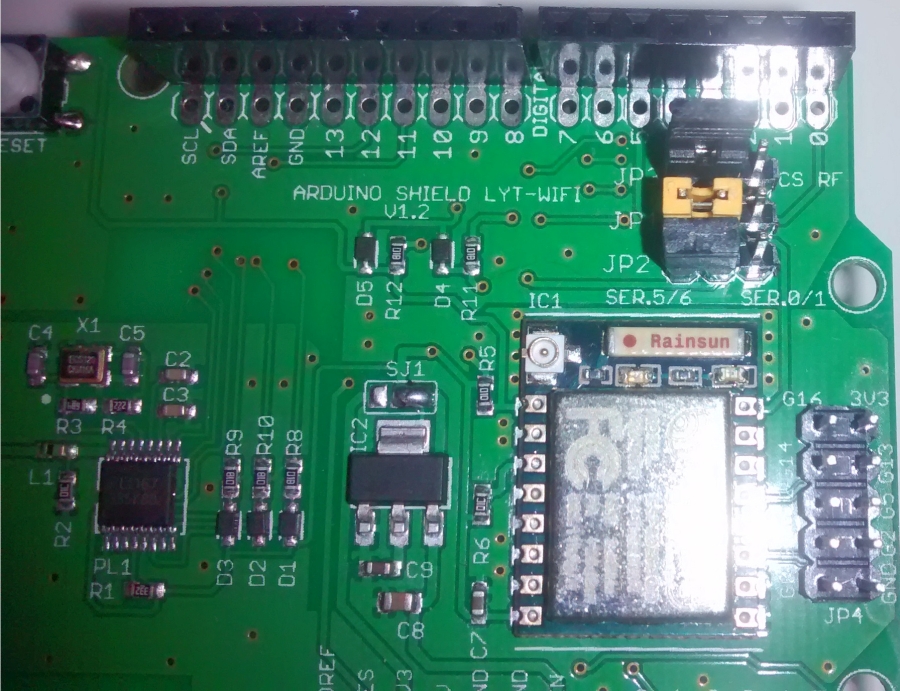
Ensure that the jumper on your shield are all on the left side as per previous picture, this means that PL1167 is using PIN10 as Chip Select (doesn’t play nice with Arduino Ethernet, be aware) and SoftwareSerial to communicate with ESP8266. Load the demo_firmware_lytwifi.ino from Examples->Lytwifi menu and start the Serial Monitor, ensure that you are matching the baudrate of your sketch (default is 9600 bps) and the Carriare Return is set, then type the following command
PON,0,0,1 This is the ON command for lamp with address 0, 0 the last parameter means that you don’t want a feedback answer from the lamp. If your lamp is properly powered, it will turn ON in full white. Turn it OFF as,
POF,0,0,1 If you want to have a fun with colors, use the following to get a RED
RGB,0,0,255,0,0,1Address of the lamps
If you have multiple lamps, you may want to control them independently, so you need to assign them a unique address (this isn’t related to the vNet address of the Souliss nodes) that can be done using
SEA,0,0,0,1 The command listed above assign the address 0, 1 to the lamp 0, 0. All lamp are shipped with 0, 0 as default address, so you should give power to one lamp per time and proceed assigning an unique address for each lamp. You are free to use the digits that you like, a suggestion is to use the first digit to identify the room and the other for the lamp.
Note down all the assigned address and relevant lamps, you will need this information while setting up the Souliss code.
If desired, you can save a pre-defined state for the lamp (ON/OFF, color and brightness) typing SAV in the Serial monitor, this will save the current state and every time the lamp is powered-on that state will be used as starting condition.
Load Souliss
As stated before, you will have two instanced of Souliss and that’s why you will found two sketches in the LYT folder. One is for the ESP8266 and the other for the Arduino board that control the PL1167.
Load Souliss on ESP8266
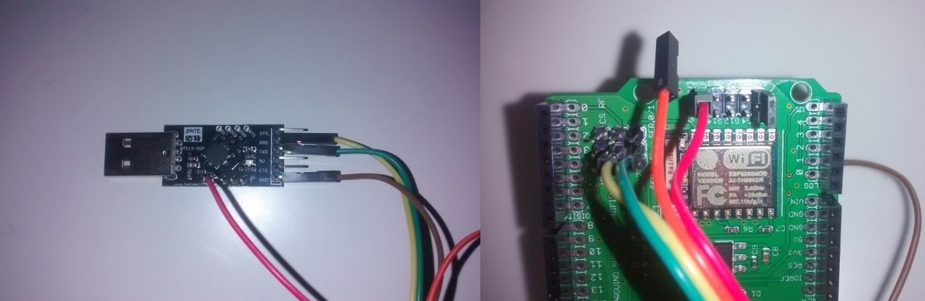
Remove the shield from the Arduino and connect the pins to a USB to USART at 3v3 as shown in the below picture (pay attention, the brown wire is connected on the back of the shield on the GND and the last two pins on JP4 need a jumper only while updating the sketch). Unsure that you are powering the device at 3v3, in the picture you can see the red wire that supply DC.
You need to setup the Arduino IDE for the support of ESP8266, this tutorial can help you if you haven’t done before; select Generic ESP8266 for the IDE menu and use 80 MHz as clock option leaving all the others at default settings.
Open the Souliss sketch for ESP8266 from the Example->souliss->LYT menu and load it, don’t forget to customize the sketch with your SSID and Password. If this succeed, you will see two empty node in SoulissApp. The IP address of the ESP8266 depends on the DHCP, so you don’t know it in advance. Generally SoulissApp detect a gateway automatically, is enough that no IP address has been set in the application. If this doesn’t work, open your router webpage and look for the assigned IP address, otherwise use Fing application for Android to get the address of the ESP8266 (look for ExpressIf as manufacturer).
/**************************************************************************
    Souliss - LYT Light Bulb

    This sketch control the Authometion LYT bubls through the Authometion
    shield.

    Load this sketch on an ESP8266 WiFi module used to bridge via USART the
	Arduino AVR microcontroller that handle the radio.
    Verify shield's jumpers and select Hardware Usart while using this sketch,
    remember to remove the jumpers before programming the Arduino. Use pin 10 as
	chip select for the radio.

***************************************************************************/

// Configure the framework
#include "bconf/MCU_ESP8266.h"              // Load the code directly on the ESP8266
#include "conf/Gateway.h"                   // The main node is the Gateway, we have just one node
#include "conf/usart_fast.h"                // USART / RS485 transceiver
#include "conf/IPBroadcast.h"

// **** Define the WiFi name and password ****
#define WIFICONF_INSKETCH
#define WiFi_SSID               "mywifi"
#define WiFi_Password           "mypassword"

// Include framework code and libraries
#include <ESP8266WiFi.h>
#include <EEPROM.h>
#include "Souliss.h"

void setup()
{
    Initialize();

    // Connect to the WiFi network and get an address from DHCP
    GetIPAddress();
    SetAsGateway(myvNet_dhcp);       // Set this node as gateway for SoulissApp

    // This is the vNet address for this node, used to communicate with other
    // nodes in your Souliss network
    SetAddress(0xAB01, 0xFF00, 0x0000);
    SetAddress(0xCE01, 0xFF00, 0x0000);
    SetAsPeerNode(0xCE02, 1);
}

void loop()
{
    // Here we start to play
    EXECUTEFAST() {
        UPDATEFAST();

        // Process the communication basic at max speed, this allow smooth handling of color and music synch
        ProcessCommunication();

        // Complete the communication tasks at normal rate
        FAST_GatewayComms();
    }
}
You will just see two empty node, because the dirty job is done by the Arduino board.
Load Souliss on Arduino
Don’t insert the shield on the Arduino, just program the board as standalone using the appropiate sketch that is always in Example->souliss->LYT, don’t forget to customize the address of your LYT (if you have changed them). Refer to the Getting Started guide for details.
Before insert the shield, ensure that the JP1 and JP2 are selected for the Hardware USART as shown in the picture below,
1
2
3
4
5
6
7
8
9
10
11
12
13
14
15
16
17
18
19
20
21
22
23
24
25
26
27
28
29
30
31
32
33
34
35
36
37
38
39
40
41
42
43
44
45
46
47
48
49
50
51
52
53
54
55
56
57
58
59
60
61
62
63
64
65
66
67
68
69
70
71
72
73
74
75
76
77
78
/**************************************************************************
    Souliss - LYT Light Bulb

    This sketch control the Authometion LYT bubls through the Authometion
    shield.

    Load this sketch on an Arduino UNO/Duemilanove (use of Leonardo require
    the use of the proper USART configuration) and using the USART bridge it
    to an ESP8266 WiFi module.
    Verify shield's jumpers and select Hardware Usart while using this sketch,
    remember to remove the jumpers before programming the Arduino. Use pin 10 as
    chip select for the radio.

***************************************************************************/
#include "bconf/StandardArduino.h"              // Use an Arduino board
#include "bconf/LYT88_LEDBulb_Radio.h"          // Define the board type
#include "conf/usart_fast.h"                    // Ethernet through Wiznet W5100

// Include framework code and libraries
#include <SPI.h>
#include "Souliss.h"

// Include Authometion libraries
#include <PL1167.h>
#include <Lytwifi.h>
#include <WiFiInterrupt.h>

// There are not used in this sketch, keep it just to pat the compiler
#include <EEPROM.h>
#include <SoftwareSerial.h>

// Define logic slots, multicolor lights use four slots
#define LYTLIGHT1           0

void setup()
{
    Initialize();

    // Set network parameters
    SetAddress(0xCE02, 0xFF00, 0xCE01);

    // Se the LYT bulbs (index, bulb type, addr_a, addr_b, logic slot), here we have
    // the first lamp (index 0) with default addresses (0, 0). Change these based on
    // the configuration of your lamps.
    InitLYT();
    SetLYT(0, 0, 0, LYTLIGHT1);

    // Define a logic to handle the bulb(s)
    SetLYTLamps(LYTLIGHT1);
}

void loop()
{
    // Here we start to play
    EXECUTEFAST() {
        UPDATEFAST();

        // Is an unsual approach, but to get fast response to color change we run the LYT logic and
        // basic communication processing at maximum speed.
        LogicLYTLamps(LYTLIGHT1);
        ProcessCommunication();

        // Here we process all communication with other nodes
        FAST_1110ms() {
            LYTState(LYTLIGHT1);
        }

    }

    EXECUTESLOW() {
        UPDATESLOW();

        SLOW_10s() {
            LYTStateRequest();              // Request the lamp state
            LYTSleepTimer(LYTLIGHT1);       // Slowly shut down the lamp
        }
    }
}
You should now be able to see two nodes and one (or more, based on your sketch) light bulb ready to be controlled.
Add multiple bulbs
If you have multiple bulbs the best option is to set for each one a dedicated address, this can be done using the } command as discussed before. Once you have your lamp with the relevant address you just need to copy/paste the relevant code and assigning a new slot and address, as example two bulbs with address 0, 1 and 0, 2 will looks like:
1
2
3
4
5
6
7
8
9
10
11
12
13
14
15
16
17
18
19
20
21
22
23
24
25
26
27
28
29
30
31
32
33
34
35
36
37
38
39
40
41
42
43
44
45
46
47
48
49
50
51
52
53
54
#include "bconf/StandardArduino.h"              // Use an Arduino board
#include "bconf/LYT88_LEDBulb_Radio.h"          // Define the board type
#include "conf/usart_fast.h"                    // Ethernet through Wiznet W5100

// Include framework code and libraries
#include <SPI.h>
#include "Souliss.h"

// Include Authometion libraries
#include <PL1167.h>
#include <Lytwifi.h>
#include <WiFiInterrupt.h>

// There are not used in this sketch, keep it just to pat the compiler
#include <EEPROM.h>
#include <SoftwareSerial.h>

#define LYTLIGHT1           0
#define LYTLIGHT2           4  // Each RGB lamp use 4 slots

void setup()
{
    Initialize();

    // Set network parameters
    SetAddress(0xCE02, 0xFF00, 0xCE01);

    // Se the LYT bulbs (index, bulb type, addr_a, addr_b, logic slot), here we have
    // the first lamp (index 0) with default addresses (0, 0). Change these based on
    // the configuration of your lamps.
    InitLYT();
    SetLYT(0, 0, 1, LYTLIGHT1);
    SetLYT(1, 0, 2, LYTLIGHT2);

    // Define a logic to handle the bulb(s)
    SetLYTLamps(LYTLIGHT1);
    SetLYTLamps(LYTLIGHT2);

}

void loop()
{
    // Here we start to play
    EXECUTEFAST() {
        UPDATEFAST();

        // Is an unsual approach, but to get fast response to color change we run the LYT logic and
        // basic communication processing at maximum speed.
        LogicLYTLamps(LYTLIGHT1);
        LogicLYTLamps(LYTLIGHT2);
        ProcessCommunication();

    }
}